Fiberglass And Plastic
In an earlier post, Temperature Control Part 2 – PC Board, I provided the Eagle 7.7 files (both schematic and board files) for the PC Board. At that time I indicated I use OSH Park (they are not paying me for this plug). As an aside, note that today’s PCB (Printed Circuit Board) is usually made out of fiberglass. Hence the title.
Multilayer PCB’s are made by sandwiching several flat fiberglass units I call slabs. When this is done with three slabs, you typically have four trace layers. Top, middle top, middle bottom, and bottom. These are called “4 layer” boards. To keep costs down, I typically aim for 2 layers which only requires a single PCB slab. These boards are fabricated faster, also.
For this project, I had earlier produced a version 2.0 of the circuit board. Version 2.0 was usable, but was generated too soon. It cost me around $35 for 3 pieces, so I went ahead and used the board. I did “flying wire” positioning of the components. This allowed me to learn from the “prototype,” which is what prototypes are used for.
At the beginning of the project, I fully expected to power the IR LED from the PSOC. It worked, but was only useful for proving the overall concept. It turns out that an IR Receiver sitting in a window is not very sensitive. You have to put quite a bit of power into the IR LED to allow reception by the AC unit if it is a foot or more from the transmitter.
I ended up creating a “Frankenstein” monstrosity of a unit that finally worked. The information gathered in this prototype kludge allowed me to determine changes for the schematic, and lead to the next version of the board. You can see the result of the flying wire build here:
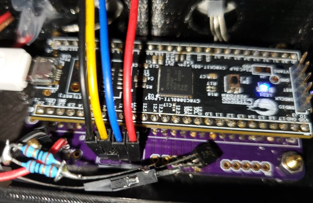
The Darlington Transistor has the center leg (the “base”) bent and shoved into the hole for the LED. The “collector” is connected to resistors paralleled in order to get the right amount of resistance to drive the LED. (This value was found by experimentation.) The “emitter” is connected to ground. The PSOC output port is pulled high through a resistor, driving the base of the Darlington does not connect it directly to the 5 volts.
The “goop” in the top of the photo is RTV. This is essentially silicone glue, but a version especially for electronics exists. It can be bought from Amazon here. Normal silicone glue cures using atmospheric moisture, and generates acetic acid (vinegar), which is corrosive, and slightly conductive. The electronics grade does not conduct electricity. It is marvelous for holding items in place in prototypes (or production models) where you expect them to be dropped or undergo vibration.
With the information learned from this experiment, I updated the schematic and circuit board files using Eagle. The updated board (version 2.1) is available for download from the PC Board post listed at the top of the page. (I did not share the previous version, although they are still good carrier boards for general purpose projects.)
Now that I had a working monstrosity, I decided to package it so I could test it in a real world scenario. The information learned from this prototype packaging goes into subsequent builds.
On To The 3D Printer — Various Mistakes in choices
About three years ago, I had a pinch in income (haven’t we all!). A development opportunity for a side project (not related to my employer’s business) came along that would not conflict with my main job, so I took it.
I used the income from that work to purchase a build-it-yourself 3D printer. (Mistake #1) I chose a PxMalion. (Mistake #2) The company’s product was on Amazon. I was also on a bit of a schedule, but the printer was fairly inexpensive. (Mistake #3).
When it comes down to it, their printer is decent, with the design hitting around a 90% to 95% successful mark. There are a few gotchas, but I am ok with my purchase. The printer never took off well enough for them to survive. I chose it because it was *cheap,* and available on Amazon, stocked here in the USA. I expected to do the build without issues. I was wrong.
The build was painful and took the better part of 2 days. I ended up making many mistakes and backtracking a lot, partly due to not understanding what I was seeing in their assembly pictures. In addition, the build was painful due to one or two critical steps left out of the instructions.
Finally a slide rod ended up being bigger on one end than the other. That one took a while to understand, and I reamed out a plastic capture before I understood what was wrong (Mistake #4). I was finally able to determine the true nature of the problem using electronic calipers. I was short on time, so ordered another printer from Amazon (justifying the expense as spare parts and meeting my schedules) and continued with the build.
The company eventually replaced the incorrect rod, without any problems. Their customer service was actually good. They had a retired military person in the U.S.A. who sourced their parts to customers. It is too bad that the PxMalion company did not survive, because their support was excellent and the product was good.
Bottom line, be prepared to support any hobby 3d printer you purchase on your own. Companies tend not to survive today, and the product production lifetime is only a few months. If you can afford it, buy two so you can have spare parts when the company vanishes.
At that time, even with purchasing two printers, the cost was much less than buying any single printer from Amazon. It was necessary for me to trade time for money, due to my income pinch. That is not something I always do, but I find I either have time or I have money. After working with the printer for several years, I am glad I have had the spare parts available. It is really a decent printer, all told. However, I won’t repeat that mistake again.
I now have a PLA printer, and after tuning, it works well. Software upgrade for ABS is available, and I did upgrade one of the boards, but I had some issues with run-away temperatures and subsequent shutdown. I am using the spare printer controller board, and may revisit the problem at some time in the future. For now, PLA is good enough for my projects.
Sketchup, AKA Drawing Plastic Parts
Sketchup is an excellent drawing program for hobbyists. Google started the company a few years ago and spun it off into its own entity. It is selling Sketchup. It is also allowing a free version for non commercial, hobby use.
After using Sketchup for several years, I feel it has a long way to go to be a solid, always go-to program for professional CAD for Models or Architecture. However, it is more than good enough for tinkering with 3D printers.
The reason I believe Sketchup is not what I would call “professional grade” it due to its habit of getting “lost in the weeds.” Several times, I have modified a modestly complex model, and when the 3D printer files were generated, the triangle file (.STL) was a disaster. Going back to the model, I found that exterior surfaces were suddenly interior surfaces.
During the process of using Sketchup, I found Netfabb. I have uploaded my broken STL files to NetFabb’s free online service for correction. A few years ago, NetFabb allowed you to download an extremely limited repair utility for hobby use. It was called “Netfabb Basic.” Their product is very good. If it is still available from them, it is worth getting.
There are some plugins that you can install for Sketchup that will fix exterior surface errors in about 50% of the cases. The rest of the time, you just have to start over. My experience with Sketchup is you want to save several intermediate versions when doing complex models. This will give yourself the ability to go back and try to make changes in different ways to avoid Sketchup corrupting your model.
Even with those issues, older Sketchup programs iare worth using for the individual. Its “push and pull” interface is extremely intuitive. One thing to note, Sketchup will be going to a subscription model soon. My experiences with their “pro” version with built in export to STL and OBJ, along with a few other features, leads me to believe paying for a “professional” version before this November might be a good idea, even for the tinkerer.
I am on the fence regarding this, but I finally tipped over. The cost is currently around $800, and at that price I feel it is almost worth it, but only for a one time purchase. Their annual renewal is $120 for the always-must-be-online one.
I have a couple of requirements for using a design program. First, my internet is spotty, so I can’t always be online. Second, my income is not steady, so I cannot agree to annual fees to keep working with a program. I almost never need technical support, so their “support” programs are a waste for me. If a program does not work, I use something else to accomplish the goal. I do not have the time to wait around for a phone call at the wrong time of day for tech support to agree their program is broken.
Note that Sketchup’s “free” version appears to be web based only. I cannot use that one because I am not internet connected 24/7. It is a non starter. If any of you have a free alternative, I am now looking.
One great thing about Sketchup revolves around the fact it is available for every major operating system. Every version reads the same files and uses the same plugins. That makes it easy to share projects with others. However the recent costs increases and 27/7 internet connectivity requirements may put it out of the reach of hobby users.
Professional Designing Tools & Windows Telemetry
But for the professional, very few programs are as good as SolidWorks. It appears to be the go-to program among the engineers I know. Very difficult learning curve, but chock full of features. It is also chock full of cost! The basic cost is about $3,300, and the annual fee is about $1,500. It is also only available on Windows.
As an aside, the Windows 10 monitoring features to “improve” the user experience according to M.S. may very well send proprietary data outside of your network. Windows 10 can, under certain circumstances, be sharing so much data back to their servers that you can run afoul of privacy laws and laws concerning proprietary information. To combat that, use SolidWorks on Windows 7, and make sure telemetry is turned off to avoid leakage of confidential and proprietary data.
For instance, Windows 10 can share your WiFi passwords over the Internet, but you can turn that off. In addition, there is a keyboard logger sending data to M.S. servers that is used to help predict words you want to use when composing documents, but you can turn that off. Notice the trend. Proprietary data is sent to Microsoft by default, but you can turn it off. How many users are able to do that?
An early Microsoft TechNet article for the Enterprise edition lists about a thousand lines of text regarding managing all the data logging “diagnostic” features. A good starting point in your research is this article: https://docs.microsoft.com/en-us/windows/privacy/manage-connections-from-windows-operating-system-components-to-microsoft-services. Also see https://www.neweggbusiness.com/smartbuyer/windows/should-you-disable-windows-10-telemetry/.
If you have to install Windows 10, install the Pro edition, and use httpd://wpd.app to lock it down (mostly). A good app to back off of MS telemetry is the free https://wpd.app.
Back to the subject at hand. So far, with SolidWorks you can get an expensive license and use it until you really feel like you have to upgrade the program. (In my case, this is usually never.) That may or may not change in the future. If your pockets are deep enough, it is probably worth it. It does require occasional internet connectivity, so there is that problem
The Nextion Display in Sketchup
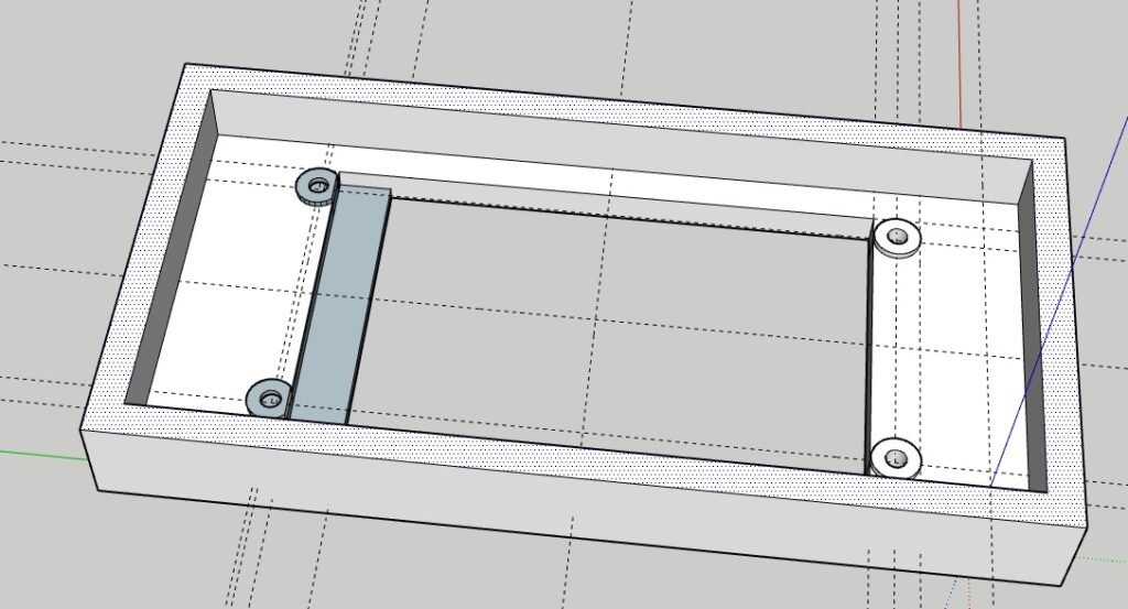
I found a hole and rectangle pattern for the Nextion display on the internet. I used the holes defined to create a Sketchup model for the front of the wall/desk mount package, as shown following. During the model work, I had an issue. In the first image, you can see that several parts of the drawing are dark.
These should be outer edges. However, they suddenly became inner edges as I was working with them. I was unable to fix them with the plugins, so I started the process over by doing a new drawing. The problem arose when I need a “lip” to cover a section of the Nextion display from the user’s viewpoint. It allowed space for a ribbon cable and other things. The damaged drawing is shown here:
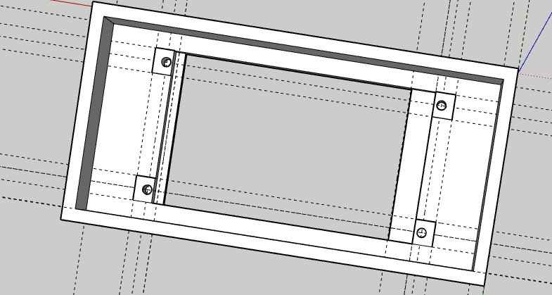
I played around with it, trying several different things. Finally, I created squares with holes in them for tap screws, and that solved the inside-out exterior surfaces,. You can download the faceplate Sketchup file here. The drawing has been corrected by turning the circles into squares for the self tapping screws:
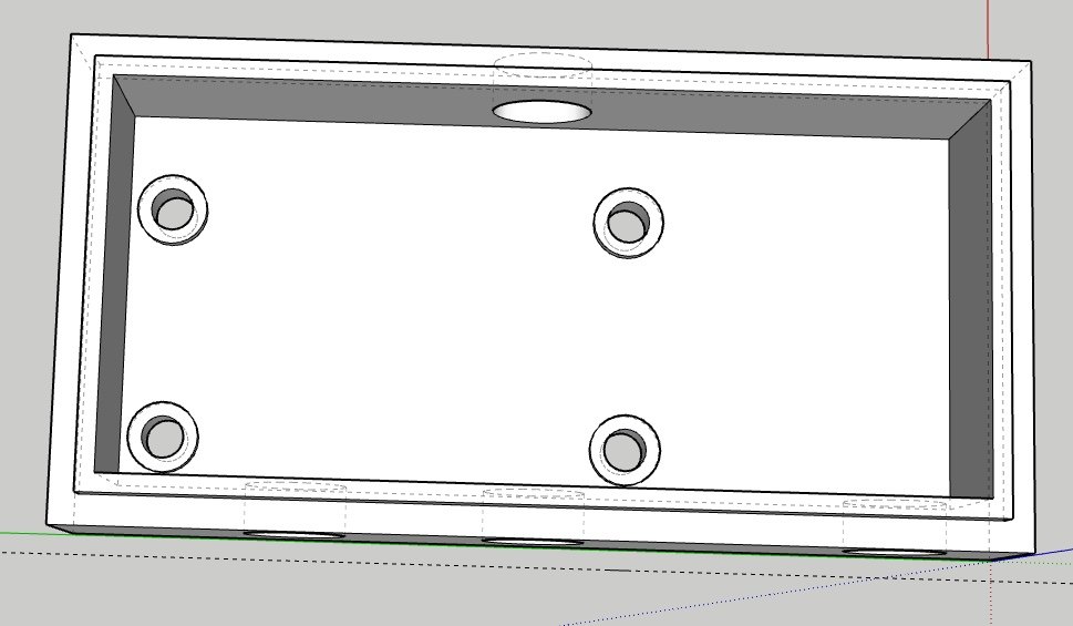
The bottom half of the case was both easier and harder. I eventually ended up with through holes requiring bolts and nuts. The case side holes are for various wires and for the temperature sensor and IR LED. The bottom design can be downloaded here. The image of the design is here:
After getting the models correct, I exported it to an STL file, and loaded it into Slic3r. Slic3r is an open source, freely available program for Windows, Macintosh, and Linux. It is available at https://slic3r.org/. I am using an earlier version, but I have never had an issue with it. It does have a difficult learning curve, but all 3D printing has a difficult learning curve.
Slic3r requires a lot of trial an error to dial in your printer. However, once dialed in, I have never had it fail. It is an excellent program and allows you to tweak almost every aspect of a build with the cheap 3D printers today.
PSOC Carrier Board in Sketchup
The carrier board back was fairly simple to design. I needed some holes for mounting the board inside the case, and for exiting of the USB cable that is powering the unit during my initial testing phase. I will probably use a 5V wall wart when powering this for normal set on table or hang on wall use. I also needed holes for the IR Led to peek out and for the temperature sensor.
The Screenshot of the holder case follows. I have a lip so the front panel snaps onto the back carrier. This took some doing, and a little work with sandpaper. I also started with white plastic and ended with black plastic as my supply ran out. I am uncertain what color the final unit will be in.
Regardless, after playing with the unit, I discovered a few of things I knew but ignored. First, heat rises. Second, LED’s generate heat when the display is illuminated. Third CPU’s generate heat when they run. Fourth, IR LED’s can be interfered with.
My DS1820B was sticking out of the top of the case. It registered a temperature at room temperature at first. It then quickly rose to several degrees above room temperature. UGH! I turned the display off with a timer, and the temperature settled down to a degree or two above room temperature. Closer.
I shoved remains of a plastic bag inside the case between the DS1820B and the PSOC. That dropped the temperature down to about 1/2 a degree above room temperature. Close enough for government work. Note to self: Put DS1820B out the side or bottom of the case in final unit. (I leave that up to you to change the model to fit your usage.)
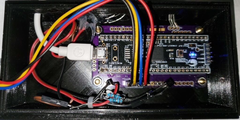
Here is a photo of the first ugly! prototype case bottom holding the PC Board and the wiring: The white connector is a USB cable. The PSOC can be powered by that cable. Cables and chargers are *cheap* so that is the route I took for this “build.”
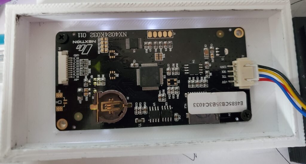
In addition, the three bare wires at the top-right are the legs of the DS1820B temperature IC. The connector (red,blue,yellow,black wires) are from the Nextion display holder top. The smudges on the case top are from press fitting onto the black case bottom. (The prototype cases were done from left-over PLA as I experimented to get the case design right.) The case friction snaps together and is pried apart with a screwdriver.
Closing Thoughts and Next Time
This post was rather long, and took more days than I expected, as I wanted to wrap the project to make it useful for you. I have some issues with the temperature control, but they are personal preferences. The great thing about open source is you can take the code and modify it for your own use.
If any of you have a suggestion for a good and easy to use open source 3d modeling program that can be used with 3d printers, let me know. Note that at work I have internet, but at home I have slow and spotty internet, so any programs must be able to be used offline.
I have ordered a version 2.1 PCB, and when it arrives I will build it (with photos) and create the final case and usage. I am waffling between white or black for the case. I have noticed the flashing blue light can be seen through a white case in a dark room, so that is useful to see if it is operating when the screen is blank due to screen power-off. (Screen is powered off to avoid heating the temperature sensor.) The PSOC generates very little heat, so it does not have to sleep between checks, based on my experience.
Check back in a couple of weeks to (hopefully) see more. I hope to cover what I have learned about 3D Printing; specifically plastics and usage from the 10,000 foot level. Very practical stuff to keep your nose happy, and your projects printing well the first time.
If you are interested in purchasing PCB’s from me, leave a comment, and I will get back to you.
Enjoy!
About The Author
W Maxfield
Firmware/hardware Engineer for too many years.