Display Part 3: Rotary Switch And Buttons
In the continuing saga of blending a CY8CKit-059 board from Cypress Semiconductors (owned now by Infineon) into the 3D printer world, I am now working on the Display. In previous posts, the inexpensive RepRapDiscount Full Graphic Smart Controller has been the bane of my programming existence.
I now have that serial beast settled out. Now comes the chore of creating a menu system that can be accessed through the rotary knob and the switch that can be pushed down. That is where I ran into trouble.
Out Of UDB’s
In about 7 years of working with the PSOC5LP from Cypress, I have never exceeded its Universal Digital Block (UDB) capability. In addition, I have found the analog component system to be more than sufficient. The underuse of UDB’s is partly due to the fact there are (often more than one) IIC, SPI, UART, PWM, USB, Timer, OpAmp, Comparator, Delta Sigma and SAR A To D, Voltage/Current DAC, Digital Filter Block, ALU, and in some cases CAN, as well as DMA units pre-created in silicon inside the device. So far, the UDB’s have been used for the occasional short falls, such as an additional UARTs, SPIs, Timers, etc.
The PSOC5LP is ideal for those one-off custom jobs for paying customers, or, in my case, at work for specialized instrumentation that needs to work at temperatures up to 350 fahrenheit (about 175 Celsius). The PSOC5LP has 24 UDB’s, containing a total of 192 Macrocells which is plenty for all the challenges I have faced. But this time was different.
Large Number Of Devices
In controlling a 3D printer, if you are obsessed about timing of pulses to the stepper motors, you need to use hardware timers. If you are obsessed about exact temperature control, you use hardware PWM’s. If you wish to communicate over USB, you need to throw that in. Serial ports need hardware UARTS. Mixed Interrupt sources need additional hardware logic. All of that is in the current 3D printer.
For example, here is a list of the units inside the 3D printer Schematic Sheets inside the PSOC5LP before the overload, all arbitrarily routed per the schematic design:
- 3 PWM’s (Fan, Bed Heater, Extruder Heater)
- 4 Timers
- 4 Pulse Converters (to stretch pulses for stepper drivers)
- 1 Clock Sync Circuit (uses Flip Flops (FF’s))
- 1 User generated Clock Divider (uses FF’s)
- 4 AND gates
- 2 OR gates
- 9 differing frequency clocks
- 1 SPI
- 1 UART
- 1 USB Controller
- 1 SAR ADC With Sequencing Analog Multiplexer to arbitrary pins
- 11 User Configured Control Registers
- 1 Arbitrary Pin User Configured, connected to an internal clock for beeper modulation
- 1 Internal Die Temperature
- 1 EEPROM Storage unit
After these were in place and being used, I added a switch debounce module. So far, so good. Then I added in a Quadrature Decoder. Boom! 196 Macrocells required, 192 available. That woke me up. I had to regroup.
First, I tried removing the press switch Debounce Circuit. Still too large. Then I went in and removed the User Clock Divider and combined some clock duties. 192 Macrocells required, 192 available. So far, so good. OOPS! Can’t interconnect everything using the switching fabric! That is also a problem for large designs in any device, such as Xilinx, Altera, etc. Oh, well.
I removed the Quadrature Decoder. Finally, Enough Room. Ok. I decided to also leave the Debounce out and debounce the press switch in code, to give me some additional space for future gates. So, here is the schematic for the Rotary Switch and the beeper on the Display unit:

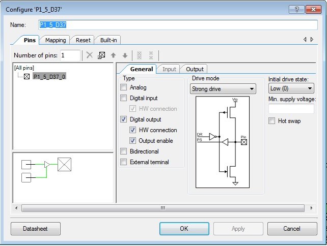
Beep
When the Beeper bit is set to 1 in the control register, the pin output is enabled, and the beeper sounds due to the Clock Signal passing to the output. Using the API functions for the Clock source, you can control the frequency of the beep at run time. To configure the beeper pin using the GUI, set it up like this:
Rotary Decode
The rotary switch is different. It was a bit of a mystery to me until I hooked up an oscilloscope and monitored the connector. It is a phase A/B encoder. (I had assumed a 00,01,10,11 encoder). If one input pin is tagged as ‘A’, and the other input pin is tagged as ‘B’, then when the switch is turned one direction, A goes high just before B goes high. Turn it the other direction, B goes high just before A.
Easiest way to handle this is with a Quadrature Decoder, which is part of the PSOC5LP built in Component Catalog. The second way to handle it is with code. So, I mucked around, failing several times. Each failure allowed me to learn something about what was going on. Contact bouncing also occurs on rotary encoder switches.
First, I found out that I needed pull-up resistors, so I configured the inputs that way. Here is the Pin Setup:

With this setup, I don’t have to worry about additional resistors on my adapter board. The pull up resistor value is around 3K ohms, per the Cypress Data Sheets. (It is buried in there, somewhere, I found it in the past. Trust me, I’m from the gov’t, I’m here to help.)
I originally had only the A pin (D33) set up for interrupt. That worked one direction, but not the other. After watching the ‘scope for a while, I realized that I had to OR the signals in order to capture both directions.
Then, I noticed that I had occasional issues reading the input pins. They were sometimes both high. Ugh. Too long. I moved the read into an ISR.
Now sometimes the pins both read low. Ugh again. The ISR was executing too fast! Reading them until one became non-zero was the trick. Since the pins were brought into a status register, a read compared against zero for one variable solved the problem with very few lines of code. In case of a glitch, (typically due to long ribbon cables), I limited the re-reads in the ISR to 10 to make sure noise in the system did not freeze the code.
After quite a bit of testing, it appears to work, for now. The resultant Encoder Read Value is sent to the Menu Task in the form of a message, so that it can handle direction in non-ISR code. (The reason to do that is because while in the ISR, no other interrupts can happen, so the system “freezes” for the amount of time it takes for the ISR to execute.)
So, here is the ISR for reading the rotary switch:
static TASK_MESSAGE_t _eTaskMessage = { cmdEncoderChange, MENU_TASK, MENU_TASK, 0, {0}};
static TASK_MESSAGE_t *eMsgPtr = &_eTaskMessage;
CY_ISR(EncoderChangeOccurred){
    int16 es;
    int16 count=0;

    es = srEncoder_Read() & 0x3;// only 2 bits are exposed
    // sometimes we are so fast we get there and the transition has
    // not finished
    while (!es && count < 10){
        es = srEncoder_Read() & 0x3;
    }

    // if es == 3, we were too slow to capture the signal.
    // nothing to do but return in that case
    // if es is still 0, then a glitch happened while both lines were
    // going negative or are both negative.  Leave in that case also.
    if (!es || es==3)
        return;

    BaseType_t xHigherPriorityTaskWoken=pdFALSE;

    ++_encoderChangeCount;// visual indicator for debugging
   // save the information into a statically allocated message
    _eTaskMessage.data[0]=es;
   // Send the encoder change message to the menu task from this ISR
    xQueueSendFromISR(MenuTaskQueue,&eMsgPtr  , &xHigherPriorityTaskWoken);

}
Pressed Switch Bounce
Push button switches don’t cleanly make contact. It is a fact of life. When you push on a button, the first few milliseconds of actuation time, the toggle part of the switch makes contact, bounces off the metal base, then makes contact again. This can happen dozens of times in a few milliseconds.
To handle this properly, can only respond to one contact. However, even low speed processors are fast enough to respond to each of those bounces that are one or more milliseconds apart. The button press is inverted with logic so the ISR responds to the button going down rather than up. That down event leads to an interrupt. Inside the Interrupt Service Routine (ISR), the last time the button ISR was triggered is recorded, and at least 0.1 seconds must have passed before the correct task in the system is notified (with a queue post of a message).
In code, the easiest way to handle the delay is to get the current system time in milliseconds and if enough time has expired since the last press, you can respond to that switch press as a “new” one. I chose 1/10th of a second. That allows the user to push the button almost 10 times per second and have the unit recognize the depresses. In human interface terms, 100 milliseconds is conceptually “Real Time.”
The code to handle that is here: (Again, we send a message to the Menu Task)
/*-----------------------------------------------------------------*/
// if the timer has rolled over (2^32)(probably won't happen, but could.
//  4 billion milliseconds is almost 50 days.)
//  then
//  take beginning ms from 0xffffffff and add to the current ticks.
//  return the elapsed time in milliseconds since 'fromMilliseconds'
/*-----------------------------------------------------------------*/
uint32_t getElapsedTimeInMilliseconds(uint32_t fromMilliseconds){
       uint32_t currentMS = getSystemTimeInMs();

    // if rollover occurred.
    if (currentMS < fromMilliseconds) {
        return (uint32_t)(((uint32_t)(0xffffffff)-fromMilliseconds)+currentMS);
    }else{
        return (uint32_t)(currentMS - fromMilliseconds);
    }
}
//-------------------------------------------------------------------
// This button handler code relies on software debounce.
//-------------------------------------------------------------------
static TASK_MESSAGE_t _bTaskMessage = { cmdButtonPress, MENU_TASK, MENU_TASK, 0, {0}};
static TASK_MESSAGE_t *bMsgPtr = &_bTaskMessage;
static uint32         _buttonTime;
//--------------------------------------------------------------------
CY_ISR(EncPressISR){
    BaseType_t xHigherPriorityTaskWoken=pdFALSE;
    // 100 milliseconds is 1/10th of a second
    if ( getElapsedTimeInMilliseconds(_buttonTime)<100)
        return; // not enough time has passed
    _buttonTime = getSystemTimeInMs();

    ++_buttonPressCount;// visual indicator for debugging
    xQueueSendFromISR(MenuTaskQueue,&bMsgPtr  , &xHigherPriorityTaskWoken);
}
Next Time
I apologize for the late post. It has been a struggle the last few weeks. I was slammed at work and at home with projects. It took some time to get back to testing the code and describing the next part of this 3D printer project. I hope to go into the Menu Task next time, doing a Text based menu for the printer that is easy to change without a lot of coding.
So far, I have plenty of code space still left inside the PSOC5LP FLASH storage. Hitting the limits on the UDB’s was a surprise.
Enjoy!
About The Author
W Maxfield
Firmware/hardware Engineer for too many years.