PSOC5LP USB Program / Debug Using KitProg3, VSCode, Mac & Linux
You can program and debug the PSOC5LP over the USB port with OpenOCD and VSCode — with some crutches. The short of it is you have to get the PSOC5’s attention with the PSOC Creator menu “Select Debug Target.”
Frustrations
I experimented with programming the PSOC using a KitProg. I have a lot of those “adapters” laying around. I currently use KitProg2 units updated to KitProg3 in order to do my debugging. The reason is those older units are natively 5 volts and all of my targets are 5 volt. I have used 3.3v KitProg 3 with 5 volt targets, and they have lasted fine. However, I fully expect they will croak one day.
Programming Failure with KitProg using PSOC Programmer
The KitProg will not program a PSOC 5 over the USB in CMSIS-DAP mode! You have to be in KitProg mode. Using an oscilloscope, I was able to prove there is no Reset Pulse from the KitProg in CMSIS-DAP mode. That is an oversight on the part of Cypress / Infineon. (See earlier posts regarding the CMSIS-DAP Mode on KitProg.)
In the KitProg Native Mode, you can program a PSOC 5. In that mode it issues a Reset Pulse. However, I was unable to debug on OpenOCD in the past in KitProg mode. I have not revisited that issue.
You cannot Debug PSOC5LP Over USB with Kitprog in CMSIS-DAP Mode using only OpenOCD. This is because you can’t get the processor’s attention using CMSIS-DAP mode.
Programming With KitProg3
You can program a PSOC5LP with a KitProg3 in CMSIS-DAP mode over the USB using PSOC Programmer. This is because the Reset Pulse is activated in the KitProg3 when using PSOC Programmer.
Debugging Using KitProg3 with OpenOCD
You can debug a PSOC5LP with PSOC Creator using a KitProg3 in CMSIS-DAP mode. And herein lies the secret. Following a simple step, you can debug over the USB using KitProg3. It may work with the KitProg, but would require switching back and forth between KitProg Native and KitProg CMSIS DAP Mode using the KitProg reset button. (See previous posts) I have not attempted that path as it is too cumbersome.
I use KitProg3 exclusively because I can use its serial port simultaneously with debugging. That allows a “debug” terminal to be used while debugging, and keeps the number of cables way down. The debug terminal shows up as a “usbmodem” connection in Mac, and sometimes as an “ACM” port in Linux. Kitprog does not support that feature, although the firmware could be updated to handle it if Infineon wanted to.
KitProg 3, First: Open PSOC Creator in your Windows VM (if on Mac or Linux)
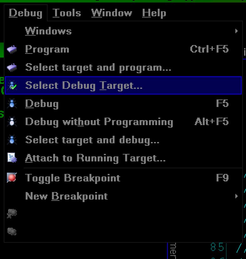
Once you are running PSOC Creator, open the project for your board. Then select the Debug Menu and go to “Select Debug Target” as shown:
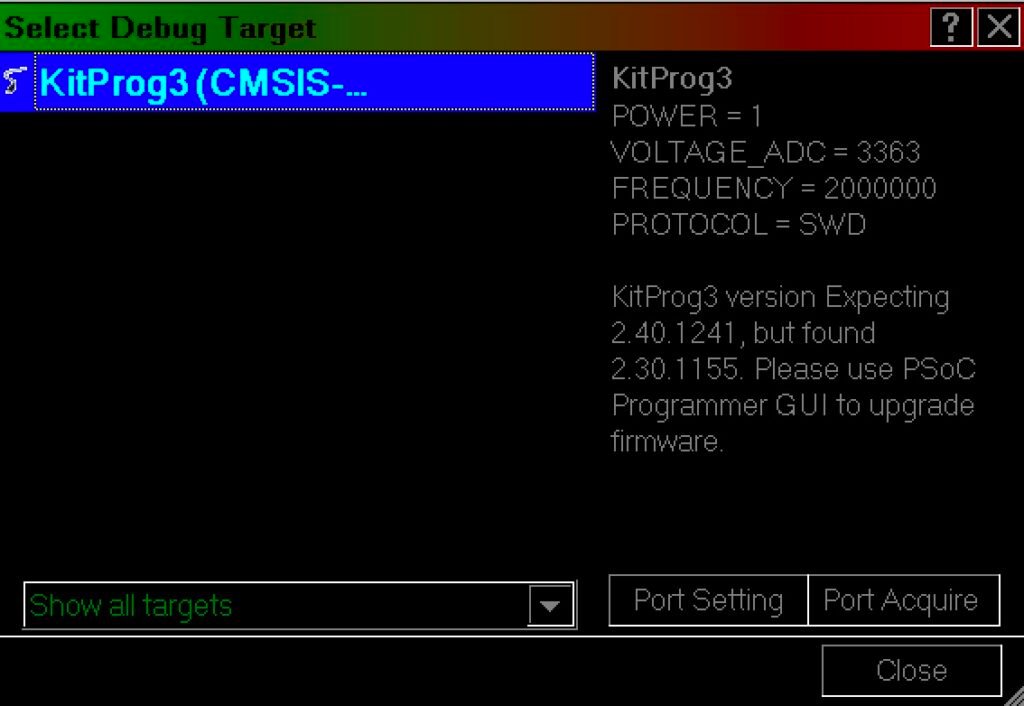
You should see the following screen show up:
KitProg 3: Second
Once you have the KitProg3 showing, check to see if your PSOC shows below the adaptor. If it does not, click on the “Port Aquire” button. Once you have done that, you should see the following:

KitProg 3: Final
Once the PSOC5 is listed, you can close the dialog. Then switch from your Virtual Machine to your native machine (in my case, a Mac). Disconnect the USB device from your VM, give the native OS some time to register the device, then start the debug process. DO NOT POWER DOWN YOUR BOARD or the KitProg3 during this time, or you will have to start over.
This works because the USB port is now the debug port and will stay that way until the PSOC is reset. Note that if you are using the USB for Debugging, you can’t use for anything else. (Obvious, I know, but we still have to label hot coffee as hot.)
Wiring The USB For Programming/Debugging
In the post https://socmaker.com/?p=1108, I covered programming the KitProg stub over its USB port. There is a picture near the end that covers the wiring with the USB signals to the 5 pin connector that MiniProg3 and KitProgs all use, along with the extra wire for doing the reset. (I will cover the fact that most USB connectors/cables use 4 wires later.)
The above referenced post also covers updating KitProg3 firmware using fw-loader.
But that is such a Kluge! Hmm. Maybe.
Yes, but there is a solution. On my board, I use a USB-Mini-B socket. The Mini-B version of USB has an extra pin, the “ID” pin. (That pin is also on the micro-USB plug and socket, for the most part.) That pin is ignored by pretty much everyone. I use that pin for the reset line into the PSOC5 LP Processor. To implement my scheme, I purchased a Mini-B cable to 5 pin terminal block cable from Amazon. (There are Mini-B to 4 pin terminal blocks, so choose carefully.) The 5th wire was soldered on the plug side to ground.
I had to get a separate Mini-B solder plug with 5 solder cups from Amazon and cut the Mini-B plug off the cable. A small matter of soldering later, all 5 pins go through to the terminal block without shorting to each other. Those were connected to a KitProg3 as shown in the post referenced above, with the ID going to the Reset signal. Presto! A “clean” pluggable connection to the board for debugging that also works as a USB port with cables that don’t use the ID pin (which is over 99% of the cables out there. The ID pin was an idea that was ignored as time went on.).
I will be putting all the ugly bits into 3d printed boxes. One box will house a KitProg for “production programming” with PSOC Programmer. The other will be for debugging just to keep stray wiring down while troubleshooting newly designed boards.
But OpenOCD Target File Can Include a SRST Command!
Yes, and No. I am still using the OpenOCD from Modus ToolBox 2.0, and that version (0.10) cannot handle the SRST command. In Modus ToolBox 3.0, the OpenOCD is 0.11 experimental, and can indeed handle the SRST command. (I moved the 0.10 version to .old and copied in the 0.11 version to prove this.)
Note that with Mac Monterey (and probably Sonoma) you have to go to the Security portion of System Preferences and allow the new version of openocd to run from the applications directory. That information is covered in previous posts, also.
The lines causing srst to be toggled are placed at the very end of the psoc5lp.cfg file in the “target” directory under the scripts directory for the openocd program. The lines placed in the file are as follows: (This info is curtesy of Mr. Nooteboom, who started me on this journey of cheap and fast debuggers for the PSOC. See previous posts.)
rename "dap init" original_init
proc "dap init" {} {
adapter assert srst
adapter deassert srst
original_init
}
The error that is shown for that set of commands is something like “Error: adapter has no srst signal.” If Infineon wishes, they can fix this. (I upgraded the KitProg3 to the latest version (2.40) to run this test.) I believe if you have a Jlink, you can use these lines without a problem.
Fini
My goal here is to provide young engineers with little pocket change the ability to debug and test their code quickly in different circumstances. In addition, experienced engineers will appreciate the ability to use something inexpensive for debugging. If you have any PSOC5 board that uses USB, you can repurpose it for your own uses with a cable, an additional wire, and a KitProg3.
After blowing up several dozen MCUs over the years, I have come to appreciate reducing the out of pocket cost of my failures as I move to a finished product. Believe it or not, 100 volt power does not mix well with 5 volt MCUs unless you are extraordinarily careful.
Enjoy!
About The Author
W Maxfield
Firmware/hardware Engineer for too many years.