Updated Temperature Board
I just receive the 2V1 carrier board from OSH Park today. Here is the blank board:
Board Top
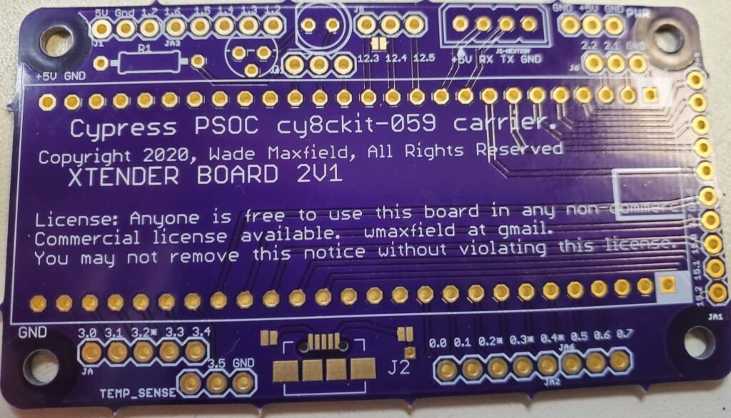
On the Front of the board, most everything is labeled. The board and carrier is powered by the 5V usb connector (outlined in white on the right side of the photo).
All of the pins are laid out on 0.10 inch centers (except, of course, for the resistors/transistors/LED and other active components. 5V is a place to provide or pull 5V. 1.2 is Port 1, pin 2, and so 0n. On the bottom right, the 0.2*, 0.3*, 0.4*, markings are for Port 0, pins 2, 3, 4. These pins have capacitors soldered on them on the CY8CKit-059 board, so are unsuitable for high speed digital I/O unless you remove those capacitors. I use them from time to time as A/D inputs and low speed digital signals and such, so bring them out to the edge.
J2 can have a USB connector soldered on, and can provide 5V to the board.
Board Bottom

The only thing of any significance on the bottom is some solder pads shown at the top. These allow you to pair up output lines from the Port 12 section (which is a high current output portion of the chip) in order to drive more current into whatever device you have.
One word of caution: On the PSOC, you are limited to about 100 milliamps total current for each quadrant of the device. There are, of course, four quadrants, and they roughly correspond to the four corners of the PSOC IC.
That limitation means you can not necessarily pull the maximum amount of current from the ports at the same time. You have to stay below the maximum current output from the device for each set of ports, based on the quadrant which powers the ports.
This limitation is explained in the PSOC data sheet, available from the Cypress website. You can get more information from here: https://www.cypress.com/products/32-bit-arm-cortex-m3-psoc-5lp
Loading the Board
Using needle-nose pliers, I bent the leads on a 1/4 watt 4.7 ohm resistor and put it into the 5 ohm resistor spot (R1). The schematic indicates 5 ohms, but that is a non-standard value. 4.7 ohms is close enough for this job. The difference in current is only 6%.
With 5 volts supply, and 2 volts for an LED, the current is calculated to be 638 milliamps, or 6/10ths of an amp. (Current = Voltage / Resistance.) The difference between 4.7 ohms and 5 ohms is 38/1000ths of an amp.
Since the IR signal is being pulsed, the average current during signaling of a “1” (LED on) is 1/2 that, so only about 3/10ths of an amp. The average wattage across the resistor (Power in watts = Resistance x Current) during signaling is 0.9 watts (almost 1 watt). Note that the average signaling current and wattage is dependent upon the number of ones occurring in the message to the A/C unit, and the time duration.
It turns out that through hole resistors can handle around 4 times the rated wattage during use, as long as the average wattage over time is low enough. Or, to put it another way, if you do not heat it up too quickly, and allow a long time to cool down, you are good. The duty cycle of this unit should allow a 1/4 watt resistor to work fine. Time will tell!
If you want to increase the wattage of your resistor set, parallel two identical resistors with exactly double the resistance you are targeting. The wattage will be exactly twice the rating of one resistor, and the total resistance will be exactly half the resistance used. This assumes the resistors are identical in all respects.
So, if you have 10 ohm resistors that are 1/4 watt, use 2 of them in parallel to get one 5 ohm 1/2 resistor equivalent. That is what I did in the prototype as you can see in the photos from previous posts. I am using one resistor that is 4.7 ohms in this version.
I pulled the PSOC out of the plastic breadboard carrier, and placed it on the board to check fit. Here is a closeup:

I haven’t soldered anything yet (other than the pins already done so it could be plugged into the breadboard), this is just to check the fit. Everything looks good. The white square on the carrier board is pin 1, it matches up with the square and white triangle next to the micro-USB plug on the CY8CKit, as you can see above.
Notice the gunk on the pins. That is rosin, left over from hand soldering, and is harmless. You can clean it off with a pencil eraser, or with chemicals that have been created for that purpose.
Note that VDD and GND on the CY8CKit matches +5v and GND on the PSOC carrier board. Those notes are for your use when you are troubleshooting and probing and the schematic is just out of reach.
Next Time
This post has been short due to scheduling issues and general busyness. Next time I will show photos of the stuffed board, soldered and unsoldered. After that, the case will be worked on to accommodate the slightly changed board. Since I bit the bullet on buying Sketchup before it became an annual $120 renewal fee, I hope to give some feedback on the 2020 version of the product.
Future
Once this board is complete and working, and the case is finished being modified, the next project is a carrier board that allows the PSOC CY8CKit-059 to control a 3D printer.
I am currently in the process of generating a basic 3D printer control system using the CY8CKit-059, FreeRTOS, and the RAMPS 1.4+ board. That project has been an eye opener for me. Very smart people have done a lot of work.
The first steps in the project is to get a very good FreeRTOS skeleton working for us. There are several FreeRTOS projects for the CY8CKit-059 out there, but they are simply proof of concept, and very bloated. I will be going through the work of making a *useful* skeleton that has very little bloat, and then doing something useful with it.
I will be open-sourcing the project. I have written the entire project myself without using any 3rd party GPL code so I can offer commercial licenses for it, should the need arise. It won’t have the sophisticated planning stuff that the current projects have, such as Marlin.
However, it also will not have the bloat, because it is not trying to service multiple versions of motherboards or chipsets. It is also a bit more of a modular design, due to being a message based system using queues and semaphores, etc. Stay tuned…
Enjoy!
About The Author
W Maxfield
Firmware/hardware Engineer for too many years.