3D Printing,PSOC, and Heat
FDM (Fused Deposition Modeling) is possible because what we call “plastic” melts, and re-melts. It can be re-melted many times, as long as you have not cooked it so much only carbon is left over. It flows from the extruder nozzle using a combination of gravity and back pressure caused by forcing plastic filament into the extruder heating area placed just behind the nozzle.
Once extruded, the plastic cools quickly and its plasticity is reduced until it enters the glass state. Cooled, firm plastic is in the glass state. For most plastics, the glass state still allows for some malleability.
For other plastics, the glass state allows it to appear be very, very solid under normal usage. For example, the PEEK plastic family (polyetheretherketone) is a semi-crystaline plastic that is very durable. You can read more about it here: https://en.wikipedia.org/wiki/Polyether_ether_ketone
3D Printers typically use ABS or PLA. (Some more description can be found at my blog here: https://socmaker.com/?p=53. You can look up the various characteristics of PLA and ABS plastic. Luckily, these two plastics are very forgiving and easy to get in filament form.
PID Controller
To properly control the heating elements of a wide range of hardware, the heating controller must be robust and reconfigurable. Fortunately, minds greater than mine have com up with a control mechanism called the PID (Proportional, Integral, Derivative) controller. This controller uses constants that can be tuned to create the temperature. I decided to use the PID controller in my printer software. The information for this controller can be found at https://en.wikipedia.org/wiki/PID_controller.
This controller algorithm can be “tuned” by a human or by the MCU running the printer. The information on doing this can be found at https://reprap.org/wiki/PID_Tuning. Someone turned this into an MIT licensed algorithm available at https://github.com/jackw01/arduino-pid-autotuner. However, baby steps.
First Step, Port The PID Algorithm
In keeping with using only Public Domain, MIT, Apache, or BSD licensed code, I searched and found an algorithm for PID control and adapted it to FreeRTOS. Along the way, I realized I needed to get the correct temperature. Ok, Pre-First Step. PID next post.
Pre-First Step, Get The Temperature
The original 3D printing platform used a 16 mhz processor, which at the time was the fastest you could get on a budget. Today, especially with the PSOC 5, you can get an 80 mhz processor which is around 5 times faster.
In order to control the temperature on the original Atmel MCU, a table was calculated from the cheap (remember, on a budget) thermistor available. The original thermistor was not linear, nor was it conducive to extremely accurate readings, but it could withstand the high temperatures involved. Due to the popularity of 3D printers these thermistors are very inexpensive today.
Thermistor Information
It turns out that acquiring information on the thermistors used in early printers requires some digging. Even today, when you buy a 3D printer kit, the thermistor is not specified. After much digging and searching, I finally tracked down the most likely thermistors in use with 3D printers. In my case, the part numbers are of interest, because I may wish to buy them to build my own printer.
Once you have the thermistor, figuring out the temperature is a multiple step problem. The original printers use a 4.7k ohm resistor to 5 volts, and derive a table of values to look up and do a linear interpolation with to determine the current temperature. There is one python table generator that I found, but not tested, at https://github.com/RichCattell/Marlin/blob/master/createTemperatureLookupMarlin.py.
Several “variables” come into play here. The first being how to measure the thermistor? Easy, the thermistor value is measured by doing a voltage measurement using an A/D. The accuracy of the reading will be affected by the accuracy of the A/D. The number of bits in the A/D is used in the table to do a binary value lookup.
The second variable is the entries in the table there (if a table is used). A table is only good for a specific thermistor, so you have to carry around a lot of tables, one for each thermistor, and include them into the compile. That is easily doable, but messy.
Using FreeRTOS, we have the luxury of taking a few hundred microseconds to calculate things like temperature. In reality, if temperature is calculated once every second or two, the temperature can be easily controlled. Therefore, the temperature control task can be one of the lowest priority tasks in the system.
The PSOC 5 library has a component, a multiplexed A/D which can be arbitrarily attached to any pin. The schematic symbol, along with configuration is here:
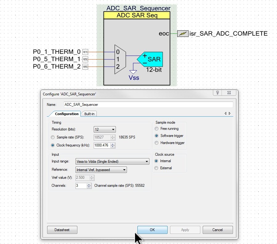
The A/D runs until all channels are sampled, and then gives an interrupt. At this point, the channels are averaged and placed in variables. The code for this work is simple in concept.
Using FreeRTOS For Temperature Calculation
First, FreeRTOS requires you “create” the task. This is usually done in a function that exists in the file that contains the task. I tend to like to keep the start task function at the end of the file so no forward references have to be used. The following code snippet contains the start task. For now, ignore the fact that two other tasks are created at the same time:
//-----------------------------------------
// set up the temperature calc tasks
//-----------------------------------------
void vAltStartTemperatureTasks( UBaseType_t uxPriorityBed, UBaseType_t uxPriorityExtruder, UBaseType_t uxPriorityCalculator )
{
    extern void initializeHeaterHardware();
    initializeHeaterHardware(); // HardwareInit.c

	xTaskCreate( vBedTemperatureTask, "BedTemp", BedTempSTACK_SIZE, NULL, uxPriorityBed, ( TaskHandle_t * ) &TaskMonitorArray[BED_TEMPERATURE_TASK].taskHandle );
	xTaskCreate( vExtruderTemperatureTask, "ExtruderTemp", HeadTempSTACK_SIZE, NULL, uxPriorityExtruder, ( TaskHandle_t * ) &TaskMonitorArray[EXTRUDER_TEMPERATURE_TASK].taskHandle );
	xTaskCreate( vTemperatureCalculateTask, "TempCalc", TempCalcSTACK_SIZE, NULL, uxPriorityCalculator, ( TaskHandle_t * ) &TaskMonitorArray[TEMPERATURE_CALC_TASK].taskHandle );
}
The Stack Size of the vTemperatureCalculateTask is three times the minimum stack size to accommodate extra room for floating point routines. The priority is just one higher than the idle task (the lowest priority in the system):
#define mainTemperatureCalculateTaskPriority ( tskIDLE_PRIORITY + 1 )     //  lowest priority, when nothing else is running
#define TempCalcSTACK_SIZE      (configMINIMAL_STACK_SIZE *3) //floating point used
Note the initializeHeaterHardware() function. It sets up the internal PWM components in the PSOC. I placed it in a file called HardwareInit.c, along with the ADC hardware initialization. Should the project be moved to different processor, at least some of the hardware based code is easier (not easy) to change due to being grouped together:
//-------------------------------------------------------------
// Initialize the heater hardware.  see Temperature.c
//-------------------------------------------------------------
void initializeHeaterHardware(){

    PWM_BedHeater_Start();
    PWM_BedHeater_WriteCompare(0);
    PWM_ExtruderHeater_Start();
    PWM_ExtruderHeater_WriteCompare(0);

}
//-------------------------------------------------------------
// Initialize the Bed Heater/Extruder Heater ADC
//-------------------------------------------------------------
void initializeADCHardware() {
    ADC_SAR_Sequencer_Start();
    ADC_SAR_Sequencer_StartConvert();
}
When using the ADC, several functions can be slightly abstracted. I use #defines to do this (for now), and so they are grouped into the functionality being used. This functionality is fairly universal, but must use PSOC dependent routines. In other SOC’s, you would use that unit’s routines:
//---------------------
// HARDWARE DEPENDENT
//---------------------
#define NUMBER_OF_ADC_CHANNELS ADC_SAR_Sequencer_NUMBER_OF_CHANNELS
//------------------------
// return ADC voltage
//------------------------
#define getADCVoltage(channel) ADC_SAR_Sequencer_CountsTo_Volts( ADC_SAR_Sequencer_GetResult16(channel))
//------------------------
// initialize the ADC
// sequencer
//------------------------
extern void initializeADCHardware();
#define startADC()  initializeADCHardware() /* HardwareInit.c */
//------------------------
// start next conversion
//------------------------
#define restartADC() ADC_SAR_Sequencer_StartConvert()
//------------------------
// return true if all
// channel information is
// ready to be read
//------------------------
#define ADCConversionIsFinished() ADC_SAR_Sequencer_IsEndConversion(ADC_SAR_Sequencer_NUMBER_OF_CHANNELS-1)
//------------------------
// END HARDWARE DEPENDENT
//------------------------

#define TEMP_25C_IN_KELVIN 298.15f
The task that calculates the current temperature does so without a table. Using FreeRTOS (and an 80 mhz cpu), we can afford to spend time calculating rather than doing table lookup. This allows us to read the data-sheet on the thermistor, enter them into a header file, and compile. Here is the calculation task. The TaskMonitor will be covered in the future, and can safely be ignored.
Using FreeRTOS facilities to run this as a very low priority task allows us to read the A/D system without directly using A/D interrupts. This frees up cycles for “important” processing.
The calculation comes from various sources. One source of options for calculation is at https://www.allaboutcircuits.com/industry-articles/how-to-obtain-the-temperature-value-from-a-thermistor-measurement/. The formula I used is an industry standard for NTC thermistors, and a calculation page is available at https://www.ametherm.com/thermistor/ntc-thermistor-calculating-the-temperature-coefficient-of-a-thermistor.
//-------------------------------------------------------------
// task that calculates the bed and extruder temperatures a few times per second
//-------------------------------------------------------------
static portTASK_FUNCTION( vTemperatureCalculateTask, pvParameters ){
 static   TaskMonitor_t *TaskMonitorPtr = &TaskMonitorArray[TEMPERATURE_CALC_TASK];
 static   int16_t        averagingIndex=0;

    (void) pvParameters;// not used
    startADC();

    for(;;) {
        // wait enough time for the A/D sequencer to finish
        vTaskDelay(pdMS_TO_TICKS(2));//Default: around 100 times per second (will vary)

        TaskMonitorPtr->runCounter++;// crude profiler

        // since this code is not using 'interrupts', we must see if the
        // SAR sequencer is done.  It should always be done
       // when we get back from the task delay
        if (ADCConversionIsFinished()){
            for (uint16 i=0 ; i < NUMBER_OF_ADC_CHANNELS; i++){
                adcVoltageReading[i][averagingIndex]=getADCVoltage(i);
            }

            restartADC();// start gathering again

            averagingIndex++;
            if (averagingIndex >= NUMBER_OF_AVERAGES)
                averagingIndex=0;

            // now average the temperatures
            for (uint16_t channel=0; channel < NUMBER_OF_ADC_CHANNELS; channel++){
                double avg;
                avg=0.0f;

                for (uint16_t i=0 ; i < NUMBER_OF_AVERAGES ; i++){
                    avg = avg + adcVoltageReading[channel][i];
                }

                // calculate the average reading over the last portion of a second .
                // This is a boxcar average.
                // Adding and dividing doubles is inefficient, however if there
                // are enough cpu cycles available to accomplish this quickly
                // enough for the human at the machine, is not a problem.
                // it makes debugging MUCH simpler.
                // It is also much less hardware dependent.
                adcAvgVoltageReading[channel]= avg/(double) NUMBER_OF_AVERAGES;
            }

            // Now calculate the temperatures
            // Plug results into the PID structures
            calculateBedTemperature();
            // only run the controller if is heating
            if (BedTemperatureOnFlag) {
                BedPID.Input = BedTemperature;
                PID_Compute(&BedPID);
            }

            calculateExtruderTemperature();
            if (ExtruderTemperatureOnFlag){
                ExtruderPID.Input = ExtruderTemperature;
                PID_Compute(&ExtruderPID);
            }
        }
    }
}
Now for the calculations. The parameters for the calculations are in a header file, Thermistor.h. The B57540G0104F000 number is the part number of the thermistor, and finding its data sheet allows for entering the values in the file:
#ifndef _THERMISTOR_H_
#define _THERMISTOR_H_
/**
 * PSOCino 3d printer firmware, FreeRTOS version
 *
 * Copyright 2020, Wade Maxfield
 * Written by Wade Maxfield
 *
 * Commercial license Available.
 *
 * This program is free software: you can redistribute it and/or modify
 * it under the terms of the GNU General Public License as published by
 * the Free Software Foundation, either version 3 of the License, or
 * (at your option) any later version.
 *
 * This program is distributed in the hope that it will be useful,
 * but WITHOUT ANY WARRANTY; without even the implied warranty of
 * MERCHANTABILITY or FITNESS FOR A PARTICULAR PURPOSE.  See the
 * GNU General Public License for more details.
 *
 * You should have received a copy of the GNU General Public License
 * along with this program.  If not, see <http://www.gnu.org/licenses/>.
 *
 */
#include "Configuration.h"


    //------------------------------------------------------------------------------
    // uncomment the version of thermistor used
    // THIS IS TEMPERATURE SENSOR #1 in most firmware tables
    #define EPCOS_100K   1           //B57540G0104F000 same as B57540G1104F000
    //------------------------------------------------------------------------------

#if BED_THERMISTOR == EPCOS_100K
    #define BED_THERMISTOR_RESISTANCE_AT_25C 100000.0f
    #define BED_THERMISTOR_BETA_25_85        4066.0f    /* 25c/85c */
    #define BED_THERMISTOR_BETA_25_100       4085.0f    /* 25c/100c*/
    #define BED_THERMISTOR_MAX_TEMP          250.0f     /* in C */
    #define BED_THERMISTOR_CALIBRATION_TEMP          25.0f
#endif

#if EXTRUDER_THERMISTOR == EPCOS_100K
    #define EXTRUDER_THERMISTOR_RESISTANCE_AT_25C 100000.0f
    #define EXTRUDER_THERMISTOR_BETA_25_85        4066.0f    /* 25c/85c */
    #define EXTRUDER_THERMISTOR_BETA_25_100       4085.0f    /* 25c/100c*/
    #define EXTRUDER_THERMISTOR_MAX_TEMP          250.0f     /* in C */
    #define EXTRUDER_THERMISTOR_CAL_TEMP          25.0f
#endif


#endif
/* [] END OF FILE */
#if STANDARD_TEMPERATURE_SENSOR_MODEL
//-------------------------------------------------------------
//-------------------------------------------------------------
static void   calculateBedTemperature(){
    double resistance;
    double analogVoltage =ReadAnalogVoltage(BED_TEMPERATURE_PIN);

    #define BED_BETA_TIMES_25C_IN_KELVIN ((double)(TEMP_25C_IN_KELVIN*BED_THERMISTOR_BETA_25_100))

    resistance  = RS_VALUE * analogVoltage /(VCC_VALUE - analogVoltage );

    BedTemperature
                = BED_BETA_TIMES_25C_IN_KELVIN /
                (BED_THERMISTOR_BETA_25_100 +
                    (TEMP_25C_IN_KELVIN * log(resistance / BED_THERMISTOR_RESISTANCE_AT_25C)))
                - 273.15f;

}
//-------------------------------------------------------------
//-------------------------------------------------------------
static void   calculateExtruderTemperature(){
    double resistance;
    double analogVoltage =ReadAnalogVoltage(EXTRUDER_TEMPERATURE_PIN);

    #define EXTRUDER_BETA_TIMES_25C_IN_KELVIN ((double)(TEMP_25C_IN_KELVIN*EXTRUDER_THERMISTOR_BETA_25_100))


    resistance = RS_VALUE * analogVoltage /(VCC_VALUE - analogVoltage );

    ExtruderTemperature
                = EXTRUDER_BETA_TIMES_25C_IN_KELVIN /
                    (EXTRUDER_THERMISTOR_BETA_25_100 +
                    (TEMP_25C_IN_KELVIN *
                            log(resistance / EXTRUDER_THERMISTOR_RESISTANCE_AT_25C)))
                    - 273.15f;

}
#endif
Reading the Voltages. This is done through a function so the hardware can be “abstracted” in the future if a different SOC is used. The number of channels is defined in the PSOC auto-generated code for the Sequencer.
The Temperature “flags” are used by the system to trigger calculation when necessary. Note that the volatile keyword is being used to force the compiler to always reference the value in memory rather than a value that could be in a register.
int16_t  BedTemperatureOnFlag; // when true, is heating
int16_t  ExtruderTemperatureOnFlag;// when true is heating


#define NUMBER_OF_AVERAGES 10

volatile double adcVoltageReading[ADC_SAR_Sequencer_NUMBER_OF_CHANNELS][NUMBER_OF_AVERAGES];
volatile double adcAvgVoltageReading[ADC_SAR_Sequencer_NUMBER_OF_CHANNELS];

double ReadAnalogVoltage(enum PinDefineEnum ChannelNumber){
    switch(ChannelNumber){
        default:
        case EXTRUDER_TEMPERATURE_PIN:// TEMP_0_PIN
          return adcAvgVoltageReading[0];
        case BED_TEMPERATURE_PIN:     //TEMP_1_PIN:
          return adcAvgVoltageReading[1];
        case TEMP_2_PIN:
          return adcAvgVoltageReading[2];
    }
}
Next Time
In the next post, I hope to go over the PID controller tasks. After that, I will tackle the possibility of having the SOC tune the PID controller on its own.
Enjoy!
About The Author
W Maxfield
Firmware/hardware Engineer for too many years.