PSOC KitProg Bonus: 5V TTL Serial UART / I2C Ports
During my projects, I often find I need a Serial UART to communicate with my devices (especially in this world of IOT). I often build in a Terminal Debugging feature which typically operates at 115,200 baud. That baud rate was difficult to consistently achieve around a decade ago, but no longer.
Once you have broken off the KitProg portion of your debugger on the PSOC CY8Ckit-059 board, the internal traces to the Serial Port portion of your PSOC Carrier board are gone. The engineers at Cypress took care of that for you during their design, before the Cypress acquisition by Infineon.
If you turn the broken off stub over, you will see the following:
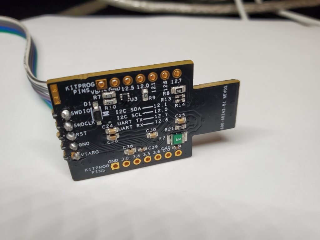
The connections are brought out to the 0.1 inch connectors at one side of the board. If you connect to the 12.6, 12.7, and ground connections, you have access to the serial port provided to you by the Cypress/Infineon drivers for Windows 7, Windows 10, Mac, or Linux.
Windows Drivers
In the Windows world, you will have to wait for the KitProg driver to be loaded from the Microsoft Servers. Once installed, any terminal program (i.e. Teraterm, Putty, Windows terminal) can be used to access the port.
Mac Drivers
On the Macintosh, the device becomes immediately available as a /dev/tty.usbmodemxxxxxx device. The xxxxx is a number which appears to be random to me.
Note that if you use the USBUart component in your project, the micro-USB, when plugged in, shows up on the Mac in the same fashion. The “screen” program can be used to access the port. (Open a terminal window on the Mac and type “man screen” to get more information.)
Linux Drivers
The USB UART (micro-USB) connector on the CY8C-Kit059 is usually under /dev/ttyACM0. It can be under ttyACM1, ttyACM2,…ttyACM9. Unfortunately, on Linux, you have to do the additional step of adding permissions to this port to make it easy to use.
To make the port world usable under Linux, then create the following file as root: /etc/udev/rules.d/50-local.rules Then, using “sudo nano” to write the file, add the following 2 lines:
KERNEL=="ttyUSB[0-9]",MODE="0666"
KERNEL=="ttyACM[0-9]",MODE="0666"
This file will be used to make the plugin of the /dev/ttyACMx world read/write/execute without running your terminal program as root. Easiest next step is to reboot the Linux machine to make this work. It is possible to manually restart the relevant services, but I am lazy.
The “screen” program can be used to access the port. (Open a terminal window on the Linux machine and type “man screen” to get more information.)
Quick and Dirty Access To The Port
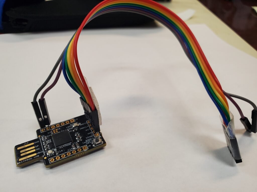
Since I was still using the CY8CKit-059 main board, I used some jumper wires to connect to the SWD debugger port on the main board from the KitProg. I used a 6 wire cable and soldered the left over pins into the holes on the KitProg. Note you can use the serial port simultaneously with debugging the PSOC.
Here is a picture of my kluge:
Next Time
Next Time I hope to start showing you the Carrier Board for the CY8CKit-059 to connect it to a RAMPS 1V4+ printer adaptor board.
The reasons I chose to do a Carrier Board, rather than a new processor design, are varied. I wanted something that would be easy for the weekend engineer. Soldering processors manually on a board using soldering irons is difficult. 0.05 width pads using a soldering iron takes *much* patience. I know from experience. Soldering 0.1 inch connector pins is relatively easy.
I also wanted a design that can take advantage of newer processors with more memory (such as the PSOC 5 on the CY8CKit-059 board). The hardware assist of the Digital/Analog Fabric inside PSOC is a marvelous bonus that makes this project snap.
In addition to all the above, there were a few economic and availability goals for this design. They are as follows:
First, the project provides PSOC 5 users with a Arduino Mega style connection bridge to the CY8CKit-059. With the connections that have been provided, you can use several shields for the Arduino. With some jumper wire, you can probably make many other shields work. However, the main goal was creating a 3d printer controller.
Second, I wanted to create a system using components and designs that can be purchased and/or fabricated within the USA as inexpensively as possible. (Think OSH-Park for the circuit board.) In addition, I wanted the components and designs to be simple enough to be replicated world-wide.
Third, I wanted any extra components to be easily purchased from places like Amazon, Mouser, Digikey, or some other distributor. I also wanted all of the sources to be available using credit cards.
So, from Amazon, fully equipped RAMPS boards are available for around the same price as the CY8CKit-059. All of the components on the carrier are available at Mouser (or Digikey), and can be bought with Credit Cards in single piece quantities.
With all that having been said, the design I will start to reveal next time has so far fulfilled the previously stated goals. I am at Revision 1V2 of the board, so it has gone through some testing. Motors are stepping, and heaters are heating, using a G Code interface.
Enjoy!
Note: I have no arrangements with Cypress/Infineon. I just happen to think their PSOC 5 is revolutionary. However, there are some new processors tied in with small FPGA’s that have shown up recently. They will bear watching.
About The Author
W Maxfield
Firmware/hardware Engineer for too many years.