PSOC 5 DAC – 1mv or smaller resolution
When dealing with the PSOC 5, you generally have a choice of 4mv (4/1000 of a volt, or 4 millivolt) resolution per bit. If you choose 4mv, you are restricted to 1.024 volts. A resolution of 16mv gives you 0 to 4 volts (approximately).
If you use the DVDAC component you can create up to a 12 bit resolution from 0 to 4 volts. Unfortunately, this involves DMA, Tables, the DAC and an Opamp, plus an external capacitor. This DAC output value is also very noisy.
As I was working with a power supply control loop, I suddenly realized I had been ignoring a simple solution to the problem of finer voltage resolution on my PSOC 5’s DAC output. Use the Current DAC! (iDAC) In my project, 10mv per step was a better choice, and easier to calculate with when outputting voltages.
If you place a 1k resistor on a pin, (use 0.1% for best results), you can get 1 mv per bit by using the iDAC in 1 microamp per bit mode. The math is simple algebra: 1 x 10e-6 X 1 x 10e3 gives 1 x 10e-3, or 1 millivolt. This gives you 0.255 volts maximum voltage. For 2.55 volts, use a 10k resistor, but that will limit you to 10mv resolution per step at 1ua current step.
It gets better once you also understand you can chose more resolution with the iDAC in 1/8 microamp per bit (up to about 32ua), or less resolution at 8 microamps per bit (up to 2 milliamps). Size your resistors appropriately for your resolution needs. With a 1k resistor, 8 microamps is 8 mv, which is twice the 16mv resolution for the voltage DAC, with a limit of 2 volts output with that combination.
The problem you may encounter is the output impedance, which for this example is 1K ohms, set by the voltage developing resistor. Any device that reads the voltage will have current flowing into it, which will change the voltage equation. (You can calculate the resultant voltage using the standard parallel resistor formula).
The rule of thumb solution is to use an opamp with high input impedance to buffer the voltage at the resistor without tremendously affecting the voltage produced due to parasitic currents. The currents are usually so small they can be safely ignored. Even so, they can usually be measured and calculated into the design.
This approach does require an Opamp with decently high input impedance. You can do this with the opamps inside the PSOC, but there are issues with this approach.
The first issue is that the PSOC’s internal aluminum cross connect wires have enough resistance to develop a voltage due to the current going through them. This voltage will be seen by the Opamp follower, depending upon how close the follower is to the iDAC output and how far away the external resistor is from the iDAC output. If the follower is close to the iDAC and the resistor is several switches away from the Opamp, the voltage output from the follower will be higher in absolute terms than the voltage across the resistor.
If you tie the resistor to the PSOC’s dedicated iDAC output pin, and force the iDAC output to its dedicated pin, this problem is greatly reduced. However, there is also another way to handle this at the cost of an additional pin.
If you connect the resistor to an arbitrary pin, and connect another pin to the same resistor, you can send the iDAC output to that pin. You will then connect an Opamp’s input in follower mode to that pin. Regardless of how the router functions, your voltage measurement will be mostly free of the resistance factors introduced by the internal aluminum wiring and cross connect resistances.
In the image following, you will see the simplicity of this solution.
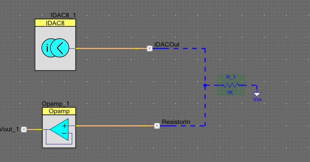
If you have an external Opamp connected to R_1 in the preceding image, you can reduce the pin count by 2. You will also loose the need for the internal Opamp, the ResistorIn pin, and the Vout_1 pin.
There are limitations, assuming a 5 volt VDDA. For the current source, you can only do 0 to 4 volts. For the current sink, you can do 5 volts down to 1 volt. Pick your values for resolution and voltage range.
With various resistors, you can get various results. In my case, I needed 2 volts out, so chose a 10K resistor, giving me 10mv resolution, which is extremely easy to calculate with. It allowed me to control a power supply with small enough voltage steps.
One strong caveat: Maximum voltage out for current source is 1 volt below VDDA. Minimum voltage out for current sink is 1 volt above ground.
So, if you have a 3.3v VDDA, you can only provide 0 to 2.3 volts DAC out, or 3.3 volts down to 1.0 volts DAC out. Keep that in mind. A 5v VDDA provides 4 volts and 1v respectively.
Enjoy!
Fini
About The Author
W Maxfield
Firmware/hardware Engineer for too many years.