Temp Sensor: 1-wire DS18B20
Years ago, Dallas Semiconductor created an unusual protocol that used the device’s input power line for communication. Using an embedded capacitor, the device can stand for power to be absent long enough to communicate to an MCU. This allows a sensor to be powered and communicate using one wire for positive voltage, and one wire for ground. Since most designs use a common ground, it was called the one wire protocol. Maxim acquired the rights to the 1-wire® devices, and manufactures them today. (®–Maximum Integrated owns the Registered Trademark for 1-wire interface.) Today’s devices typically keep power and ground always connected, and communicate on a third connector using the protocol.
Sources of Information about 1-wire® and PSOC
There have been several forum posts and blogs written about communicating with those devices. Maxim has a page on these devices here: https://www.maximintegrated.com/en/design/technical-documents/app-notes/3/3989.html. An old blog post on using this protocol can be found here: https://wphost.spider-e.com/?p=234. Cypress community forum posts exist several places. One is here: https://www.cypress.com/comment/202076
GPIO and 1-wire®
The PSOC 5 is ideally suited to communicate to 1-wire devices. If you initially look at the specs, you would normally assume that you need at least an external resistor. This is not the case for the PSOC 5, with its configurable GPIO pins.
What is not obvious on the PSOC, (unless you read *all* of their documentation) is if you configure the output parameters on a GPIO pin, it also configures the input parameters on that pin. So, if you need a pull-up resistor on a pin’s input, configure the output to be a resistive pull-up with a default power-on output level of 1. Doing this provides you with a resistor that is usually around 5,000 ohms (5 K ohms), but can be as low as 3.5K ohms, or as high as 8.5K ohms.
A value of 5,000 ohms typically provides about 1 milliamp of current into a pin shorted to ground when resistive pull up is used and VDD is 5 volts. This is enough to power a DS18B20 device parasitically. The data sheet specifies a 4.7K resistor to power for parasitic power, but there is always some leeway.
Device Configuration
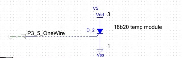
First, put a pin on your schematic. Select Digital Input from the Components on the right hand side, under the “Cypress” tab. Also click to the “Off-Chip” tab and select an SCR. Put it on the page and wire it up using the “External Connection” option on the Pin Configuration Editor. Here is what mine looks like, (and it took some time to find all the parts):
The Pin connection to the IC pin is configured in the “Design Wide Resources” in the left side panel. Click the “+” and click on pins. Use the Port column drop-down to set the pin to Port P3 [5].
The PSOC 5 Pin that talks to the 1 wire bus now needs to be configured for our task. To do this , double click on the pin on the schematic, or right-click on it and choose configure from the pop-up menu.
I have set it up as neither an input nor an output. See the following image:
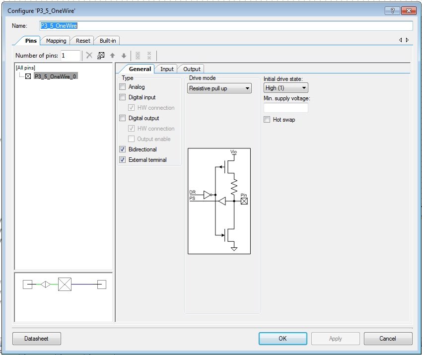
Note that the Pin has Neither Analog nor Digital input checked. (However the Digital Input and Digital Outputs have the HW connection checked.) I first checked these boxes, made changes, then unchecked them. The External Terminal is checked so I could get a blue line to connect to it from the external device for my schematic. The pin is configured as Initial Drive state High (1). You may need to enable the input buffer to get a reading.
The name of the Pin is P3_5_OneWire. I have started following this naming pattern in self defense; my memory is not what it used to be. PSOC Creator allows you to rename the pins to be anything. I now name them P (for port) 3 (for port 3) _ 5 (for bit 5) _OneWire (what I use it for). I then assign the pin number for the pin in the .cydwr (System wide design resources) pins screen, as P3[5], using the drop-down selection under the Ports column.
With this naming system, I always know what the pin is. I know where to find it on the PSOC. I also know where to look on the schematic as I debug my code. It saves a lot of time during late hour debug sessions.
The Code
Here is the code for reading the temperature device. First, the Header file. Note that the ideas behind some of this code was compiled from many sources on the Internet. So feel free to use this to create your own should you not wish to copy directly. The file is ds18b20.h:
#ifndef _DS18B20_H_
#define _DS18B20_H_
/* ========================================
 * Copyright Wade Maxfield, 2020
 * All Rights Reserved
 * LICENSED SOFTWARE.
 *  Under the GPL v3 license
 * This license does not override previous licenses
 * Some information may be Proprietary to
 * Cypress (http://www.cypress.com) for their
 * PSoC 5LP®--Cypress Semiconductor and
 * only usable on their devices.
 * PROPERTY OF Wade Maxfield.
 * Commercial license available
 * ========================================
*/

#include <project.h>

    // commands to device
#define Skip_ROM 		             0xCC
#define BeginTempConvertion 		 0x44
#define Read_scratchpad              0xBE

#define TIMEOUT_READ_WRITE_0_BIT    50           //Data bit 0 read,write 15-60us
#define TIMEOUT_READ_WRITE_1_BIT    10          //Data bit 1 read,write 1-15us
#define WAIT_TIME_US                480         //in us.(minimum 480)

/***************************************
*        Function Prototypes
***************************************/

float getTemperature();// return temperature Celcius
float getTemperatureF(int16 * readingAvailable); // return temp Fareignheight

void initialize_1_wire_device(); // initialize system

uint8 OneWireResetResults;

uint8 Read1WireBit();
uint8 Read1WireByte();

uint8 Reset1WireBus();

void Write1WireBit(uint8 payload);
void Write1WireByte(uint8 payload);

/*    Here are the "family" definitions for 1 wire devices
uint32 Family;
		case 0x00:             Family=0;    // unknown
        case 0x01:             Family = 0x1990;
        case 0x02:             Family = 0x1991;
        case 0x04:             Family = 0x1994;
        case 0x05:             Family = 0x2405;
        case 0x06:             Family = 0x1993;
        case 0x08:             Family = 0x1992;
        case 0x09:             Family = 0x1982;
        case 0x10:             Family = 0x1820; // temperature
        case 0x28:             Family = 0x18B20;// temperature
*/

#endif

/* End Of File */
Next is the C file. I will cover the non-traditional parts of it later. The file is ds18b20.c:
/* ========================================
 * Copyright Wade Maxfield, 2020
 * All Rights Reserved
 * LICENSED SOFTWARE.
 *  Under the GPL v3 license
 * This license does not override previous licenses
 * Some information may be Proprietary to
 * Cypress (http://www.cypress.com) for their
 * PSoC 5LP®--Cypress Semiconductor and
 * only usable on their devices.
 * PROPERTY OF Wade Maxfield.
 * Commercial license available
 * ========================================
*/

#include <ds18b20.h>
#include <stdio.h>

//--------------------------------------------
// These defines are used to make it easier
// to change pin names.
//--------------------------------------------
#define OneWire_Read    P3_5_OneWire_Read
#define OneWire_Write   P3_5_OneWire_Write

uint8   OneWireResetResults;
char BUFFER[16] = " " ;  // buffer for 6 bytes SERIAL NUMBER
uint16  OneWireError;


//--------------------------------------------
// initialize the one wire subsystem
//--------------------------------------------
void initialize_1_wire_device()
{
    uint16 ReadHEX ;

    OneWireResetResults = Reset1WireBus();
    Write1WireByte(0x33);
    ReadHEX = Read1WireByte();
    // flag an error condition if it occurred
    if (ReadHEX != 0x28 && ReadHEX != 0x10)
        OneWireError=1;

}
//--------------------------------------------
// read a bit from the device
//--------------------------------------------
uint8 Read1WireBit()
{
    CyDelayUs(20);
    OneWire_Write(0);    // signal want to read
    CyDelayUs(TIMEOUT_READ_WRITE_1_BIT);
    OneWire_Write(1);    // send pin high so can read device response on line
    CyDelayUs(5);
 	return(OneWire_Read());

}
//--------------------------------------------
// Write a single bit to the  bus.
//--------------------------------------------
void Write1WireBit(uint8 payload)
{
    CyDelayUs(20);  //Inactive period
    OneWire_Write(0);

    if(payload==0)
        CyDelayUs(TIMEOUT_READ_WRITE_0_BIT); //0 write
    else
        CyDelayUs(TIMEOUT_READ_WRITE_1_BIT); //1 write

    OneWire_Write(1);       //Send High
}
//--------------------------------------------
// reset the device bus
//--------------------------------------------
uint8 Reset1WireBus()
{
    uint8 BusPin=0 ;

    OneWire_Write(0);

    CyDelayUs(WAIT_TIME_US);

    OneWire_Write(1);
    CyDelayUs(5);

    if (OneWire_Read()==0)
        return(0xFF);   //the line is shorted, exit with error indication.

    CyDelayUs(55);

    // read the value on the pin
    BusPin = OneWire_Read();
    CyDelayUs(200);     // wait for temperature sensor to be done

    return(BusPin);
}
//--------------------------------------------------------------------
// Write a byte to the serial bus
//-------------------------------------------------------------------
void Write1WireByte(uint8 byteToWrite)
{
    uint8  shiftcount;

    for (shiftcount=0; shiftcount<=7;shiftcount++) {
        Write1WireBit((byteToWrite >> shiftcount) & 0x01);
    }
}
//--------------------------------------------------------------------
// Return a byte read from the serial bus
//--------------------------------------------------------------------
uint8 Read1WireByte()
{
	uint8 IncomingByte=0, shiftcount=0 ;
	for (shiftcount=0; shiftcount<=7; shiftcount++)
    {
       IncomingByte |= (Read1WireBit())<<shiftcount;//let's start with LSB
    CyDelayUs(6);
    }
    return(IncomingByte);
}
//--------------------------------------------------------------------
// Temperature reading.
//--------------------------------------------------------------------
float celcius=25.0;

//--------------------------------------------------------------------
// we use a state machine to direct the process of reading the temperature.
//--------------------------------------------------------------------
enum TemperatureReadState {
    nothing=0
    ,start
    ,waitForRBit
    ,readTemperature
    ,readStaticRamFromTempSensor
    ,tempAvailable
};
enum TemperatureReadState TemperatureState=nothing;

//--------------------------------------------------------------------
// Return the temperature in celcius
//--------------------------------------------------------------------
float getTemperature()
{
    static int16 i;
    static uint8 staticRamBytes[8];
    int16_t a2dReading;

    switch (TemperatureState){
        case nothing:
            TemperatureState = start;

        case start:
            Reset1WireBus();
            Write1WireByte(Skip_ROM);
       	    Write1WireByte(BeginTempConvertion);
            TemperatureState = waitForRBit;
        break;

            // NOTE: we don't have to wait for any time
            // to read this, since we are always powering the device
        case waitForRBit:
            if (!Read1WireBit())
                break;
            TemperatureState = readTemperature;

        break;

        case readTemperature:
        	Reset1WireBus();
        	Write1WireByte(Skip_ROM);
        	Write1WireByte(Read_scratchpad);

            CyDelayUs(1);
            TemperatureState = readStaticRamFromTempSensor;
            i=0;
        break;

        case readStaticRamFromTempSensor:
            staticRamBytes[i]=Read1WireByte();
            i++;
            if (i<8)
                break;


            a2dReading = (staticRamBytes[1] << 8) | staticRamBytes[0];

            a2dReading  <<= 3; // 9 bit resolution default

            //if sensor is ds1820 or ds18s20 only 9 bit
            // calculations. See datasheet!
            if (staticRamBytes[7] == 0x10){
              // remaining count gives full 12 bit resolution
              a2dReading = (a2dReading & 0xFFF0) + 12 - staticRamBytes[6];
            } else {
                //if sensor is Ds18B20 9 through 12 bits are available
                int8 configuration = (staticRamBytes[4] & 0x60);
                // if lower res, the low bits are undefined
                switch (configuration) {
                    case 0:
                        a2dReading &= ~7;  // 9 bits,takes 93.75 ms
                    break;

                    case 0x20:
                       a2dReading &= ~3; // 10 bits, takes 187.5 ms
                    break;

                    case 0x40:
                        a2dReading &= ~1;  // 11 bits, takes  375 ms
                    break;

                    default:
                        // default is 12 bit resolution,
                        // takes a full 750 ms conversion time
                        // so we need to time-slice readings so as
                        // to not freeze the rest of the system
                    break;
                }// switch
            }//else


            celcius=a2dReading/160.0f;
            TemperatureState = tempAvailable;
        break;

        case tempAvailable:
            // hang in this state until we are restarted
        break;
    }

    // return old values until new value exists
    return celcius;

}
float TempF=70.0;

//--------------------------------------------------------------------
// return the temperature in degrees F
//--------------------------------------------------------------------
float getTemperatureF(int16 *readingAvailable){

    // if a non-zero passed in, assume we can write to it
    if (readingAvailable)
        *readingAvailable=0;// indicate no reading is available

    getTemperature();//run the state machine, ignore return

    if (TemperatureState == tempAvailable){
        TemperatureState = nothing; // restart reading next time
        TempF = celcius *1.8f+32.0f;// we are using the global, could use return
        // indicate we have a reading
        if (readingAvailable)
           *readingAvailable = 1;
    }
    return TempF;

}

/* [] END OF FILE */
Explanation of Code
The temperature() code uses a state machine to read the temperature from the device. This is critical, since the PSOC needs to be able to do other things for our project while reading the temperature from the device.
This state machine is implemented in C as a switch. You stay in a “state” until the code in that state “transitions” you to the next state, based on decisions made on external data. This machine most closely resembles a Mealy State Machine. (see https://en.wikipedia.org/wiki/Mealy_machine.)
The transitioning of the state is done through the switch statement variable. Changing that variable changes the state. I use an enum to define the states and the variable that holds the state. This allows the C compiler to warn me if I try to assign an invalid state, or if I forget one.
The temperature() routine runs the state machine each time it is called. When a new reading is available, it sets the reading available flag. By watching that flag, you know when a new reading is available.
With a state machine, your code can revisit slowly operating external devices, and only spend uninterrupted time on them when data is forthcoming. In this case, waiting for the temperature reading can take almost a millisecond. If you were to read temperature as often as possible (like we are doing in this example), then there would be almost no time left to do other work, and your MCU would appear to be very sluggish.
Typical Usage
To use this code module, you first call initialize_1_wire_device(). After that, call getTemperatureF(), until a reading is available. The globals celcius, and TempF will hold the degrees C and degrees F. (I got lazy during naming of variables. I am only using the degrees F in my project).
Here is what the code in main() would look like:
#include "project.h"
#include "USBSerial.h"
#include "parseCommands.h"
#include "ds18b20.h"

int16_t TemperatureReadingAvailable;
float temperature;
main()
{
 // the following two variables are for USBSerial/Command Parser
    int16 bufNum;
    USBSerialMessage *USBRxPtr;

    initialize_1_wire_device();

    CyGlobalIntEnable; /* Enable global interrupts. */

    /* Place your initialization/startup code here (e.g. MyInst_Start()) */
    initUSBSerial();// setup the USB serial interface.
    init_parse();

    for(;;)
    {

        //======================
        // usb serial port
        //======================
        if ((bufNum=handleUSBSerial())>=0){
            USBRxPtr=&USBRxBuffer[bufNum];
           parse((char*)(USBRxPtr->msg),&(USBRxPtr->size)); // handle possible command

          temperature=getTemperatureF(&TemperatureReadingAvailable);
          if (TemperatureReadingAvailable) {
             // write your code here to do something
          }
       }

    }
You should be able to step through the code with the debugger and see how it works. You can’t step through the Read/Write 1 bit and Read/Write 1 byte functions, but you can examine their actions on an oscilloscope.
It is instructive to do a few temperature readings using breakpoints in the debugger, and then hold your finger on the ds18b20. You should see about a 5 degree rise in just a few seconds.
Next time, if life permits, we will add reading temperature to the USB terminal.
Enjoy!
About The Author
W Maxfield
Firmware/hardware Engineer for too many years.
Hi Wade, I’m trying to implement this code, with the difference that I’m using a LCD 20×4, it already gives me a temperature but it’s not okay, the real temperature in the room is 29ºC and in the LCD I see 24ºC. I tested the sensor with an arduino and it gives me the correct temperature. Do you have any idea of what is happening? However I’ll continue trying to guess what is happening. I hope you can help me, thanks
There could be a couple of possibilities. Analyzing, the temperature of 29 is binary 00011101, and the temperature of 24 is 00011000. That should be easy to see on an oscilloscope. If it is the exact same part, if you are using the PSOC5 pullup resistor, it is possible that the 3k resistor that port provides is too low for the temperature sensor to handle. Try using a 10k resistor and configure the pins for high impedance.
Another possibility is the timing on the PSOC is just a bit off. It may be losing the lower bits.
Try using a logic analyzer (you can get a HiLetGo analyzer from Amazon for $12.95). The PulseView program (search google for PulseView) works with it, and you can see if your PSOC is reading the data correctly by comparing the bits inside the PSOC to the ones the analyzer tells you.
Hi wade, Im trying to implement this code with a CY8C5888LTI-LP097 (CY8CKIT-059 PSOC 5LP), i did everything as you said, with the diference that i show the temperature in a LCD 20×4, the real temperature in the room is 29 °C but the lcd shows 24.5°C. i tested the sensor in an arduino and it works ok, i mean i can see the 29°C. I hope you can helpme.
I have a downloadable project that includes the one-wire temperature sensor plus other things. it is at https://socmaker.com/?p=703
You can use that code to compare to your code.
Dear W. Maxfield,
I am currently working on a project where I am trying to implement the DS1820 temperature sensor using the PSOC 5LP. However, I do not require the temperature to be displayed on an LCD at this stage. Instead, I am looking to create a log file where the temperature for a given time is stored, which will later be sent to a display.
I am currently facing some difficulties implementing the onewire protocol using the PSOC, even though I have successfully used it before on an Arduino. Therefore, for now, I am just trying to read the temperature data from Realterm using UART.
I was wondering if you could offer any guidance on how I could achieve this or if any changes to the code would be necessary.
Thank you for your time and any help you can provide.
Hi Utka,
In subsequent posts, I have included the PC board and the entire project. You are welcome to take that code and use it.
The code is fairly modular. The temperature gathering is separate from the display, so you should be able to create a module that logs the data.
Enjoy your journey!
Hi Wade,
Really helpful bit of code. In Device Configuration you may want to advise your readers to check Input buffer enabled in the Imput tab otherwise a read always gets a zero. Although you detect errors theres not much in the way of debug messages.
Cheers and well done saved me alot of time.
Paul