Testing The Project
If you are like some of the readers, you are very interested in the project as a complete whole. To that end, you can download the project from here. It an archived bundle, zipped up. Unzip it and load the project in PSOC Creator.
If you are using VMWare on a Mac (like I am), then you need to make sure the KitProg device is attached. Once it is attached, you can load the project into your board. My board is plugged into two breadboards which have been modified on a carrier to be a certain distance apart.
This distance allows the CY8CKIT-059 to be plugged in, with all of the connection row available on both sides of the board. I also directly plugged in a logic analyzer and then use jumper wires to wire to the ports I am interested in testing. Makes it much neater, and easy to leave set up from one week to the next, or one project to the next.
If you have not seen the setup, or need a refresher, here it is again. The USBUart is plugged in on the left side of the photo, the KitProg (along with the RS232 Uart) is plugged into the right side:
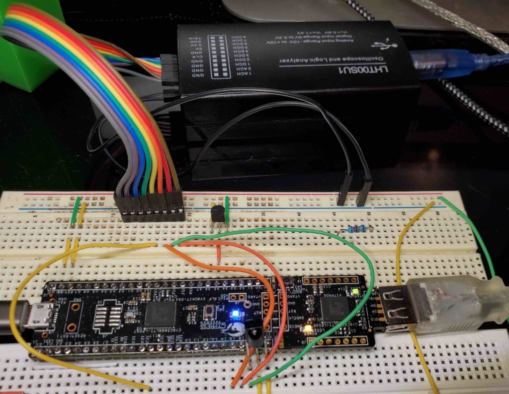
In our project, the RS232 Uart uses pins 12[6] and 12[7]. The engineers at Cypress thoughtfully wired those pins into the Uart section of the KitProg. By doing this, we can communicate from our board over the Uart to a Communication Port (COMxx) on Windows.
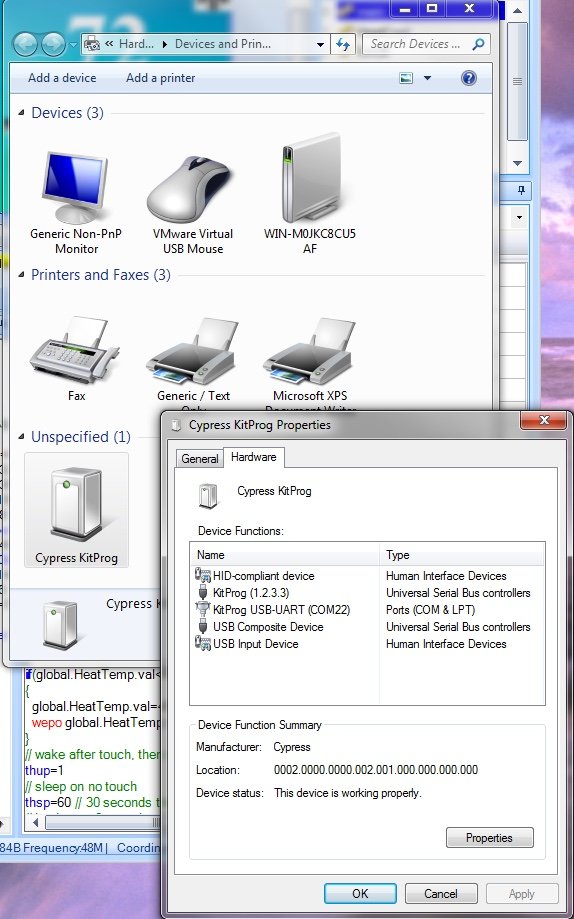
Make sure your KitProg shows up in your Devices Section of Windows. Once it does, then Right-Click on the device, and the COM port (in this case COM22) will be shown to you. That is the port you will connect to the RS232 Uart on pins 12[6] and 12[7]. Here is a snapshot of that:
Load and Run PSOC Creator in Debug Mode
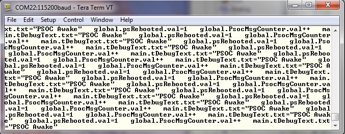
Run PSOC Creator, Load the project, run it in debug mode (if you wish). Once you do that, you can load up a Serial Communications program (I use TeraTerm or Putty), and you should see something like the following when you connect to the COM port (in my case COM22– your port will be different):
Close that program, and launch the Nextion IDE. Position the two IDE’s for your comfort. Load the Thermometer program in the HMI. Re-adjust for fitting. Mine looks like this:

Run the Nextion Debugger
The Nextion has a nice “debug” feature that will run the project where you can test each screen. You can also use the computer’s COM ports and connect to your PSOC, virtually testing the interaction with the Nextion hardware. This is a very powerful feature, and saved me a lot of time once I was able to determine exactly how to put the pieces together.
NOTE: If you break the debugger off of the CY8CKIT-059 board, the link to pins 12[7] and 12[6] are permanently broken. Your debug trick will stop working. You can use jumper wires to reconnect to the pins 12[6] and 12[7] on the debugger stub, but doing that is rather painful. I dislike soldering at this point in my life!
Click on the Debug button in the Nextion IDE. On the screen that shows up, click on the “User MCU Input” radio button. The COM Port and Baud Rate drop downs need to point to the COM port that KitProg showed for its USB-Uart, and the data rate chosen for this project, which is 115,200. Like this:

You can click on the S on the Simulator Return and MCU return to get a string representation of the messages being sent between the PSOC and the Nextion. You are now able to walk through the screens, testing each one with your PSOC code in the PSOC Creator.
The RS232-Uart
In the PSOC, the Uart is a hardware based device. With the functions that Cypress provides, the Uart is very easy to use. In our case, we only use the Receive Interrupt. Our messages being sent are small enough to fit into the transmit buffer we have chosen, so we use the Cypress routines for that purpose. (Behind the scenes, Cypress provides an interrupt driven transmit, but we don’t have to manage that part of it unless we want to.)
Next Time
This has been an interesting few months. With various interruptions, this project is behind the schedule I set for it, in terms of showing to you. I have it working in my home office, controlling the window unit. There are a couple of things I will probably change, but since you have the project, feel free to make your own changes.
I hope to bring Sketchup into the picture for the next part of the project. After that we will move to the 3D printing of the box the AC unit controller lives in.
Enjoy!
About The Author
W Maxfield
Firmware/hardware Engineer for too many years.