Firmware Update CY8CKit & Temp Sensor Preview
Once you receive your kit from Cypress, you need to update the debugger’s firmware on on the board. Cypress makes it easy if you are running a Windows machine, but using VMWare makes it more complex as a guest operating system. I describe it as a dance. With the proper dance moves, the process is accomplished.
First, remove the board from the package, and plug it into the USB. Under VMWare, the KitProg will be connected to the Windows machine (see the previous post for setting that up), and the drivers will take a *long* time to install. They have to be downloaded from Microsoft Central. During this period of time, you can show the progress screen, and it will look like this:

Once the drivers are loaded, with “Ready to use” checks for all the parts, your are ready for the next step. Try not to interrupt this process, otherwise you will have problems in the future, some not easily resolved.
Upgrading KitProg Firmware: Dancing With VMWare
Start the PSoC programmer. The version shown at the time of this writing is 3.28.6. It will show the KitProg. It may show a blue indicator next to the KitProg. If not, click on the KitProg text line:
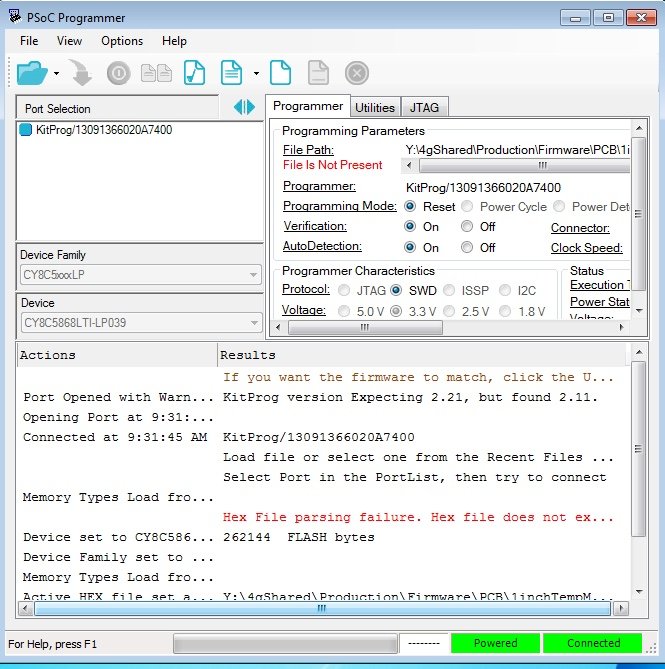
Start the Upgrade
You may see a warning message about Expecting a certain version (in this case 2.2.1). This warning message indicates the KitProg firmware is out of date. You can fix this. To start the process of updating the firmware, click on the “Utilities” tab. Click on the “Upgrade Firmware” button. You will immediately get a failure notice for the firmware update:
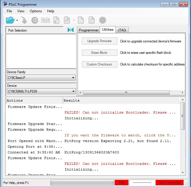
This is because the PSoC on the KitProg rebooted and identified itself as a bootloader. Your next step is to go to the VMWare Menus and select: Virtual Machine -> USB and Bluetooth -> USB & Bluetooth Settings…
At this time, the USB and Bluetooth dialog will show that KitProg is not in the list, but Cypress KitProg Bootloader is:

Click on the checkbox next to the Bootloader. Don’t dismiss this dialog, it will be used again, soon.
The Bootloader will be connected to Windows, and you will be given an error in the programmer utility, indicating the bootloader devices is detected:
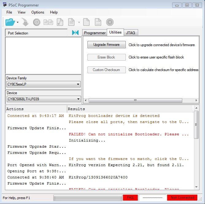
At this point, you must click on “Upgrade Firmware” button again. You will probably get an Exception notice from Microsoft’s .NET runtime, giving you an option to quit or continue. If this happens, click “Quit,” and restart the PSoC Programmer.
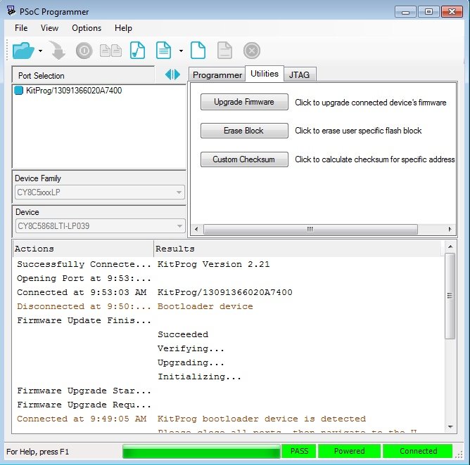
Click on the “Utilities” tab. Click on “Upgrade Firmware” button. You will see statements in the actions area and graphs at the bottom of the screen, while the firmware upgrade is finishing. At this point, the bootloader will be disconnected, and the KitProg will show up in the USB & Bluetooth dialog again. You must act to re-connect it to Windows.
Click on the checkbox next to the KitProg device to connect it to windows. It will show up in your list in PSoC programmer and indicate its KitProg Version is 2.21 (at the time of this writing).
You have to do this dance every time the KitProg has to be upgraded, if you are running VMWare. Unfortunately, a USB plug event does not appear to be given to VMWare’s Window guest when the KitProg boots into the bootloader, so this dance is necessary. It happens frequently enough that I documented it, but not so often that it becomes an ongoing annoyance.
Next Time, USB UART
We will start setting up for temperature measurements soon. If everything goes to plan (does it ever?), I will show you how to create a user interface to your PSoC. You will be able to read measurements off of the temperature sensor onto your screen using the USB UART.
Temperature Sensor
In one of our next posts, we will play with OneWire® and temperature readings. To do this, you will need a DS18B20 temperature sensor. I ordered mine from Amazon by doing a search for DS18B20, and got several choices. I picked the one that was 10 pieces for $9.99, so I could blow some up and install some in projects like this one. It is best for our testing to choose the 3 legged kind, they are very easy to plug into a breadboard.
To attach to the PSoC®, you will use the ability of the PSoC® GPIO Pins to provide you with pull up resistors on inputs. Here is a pin connection diagram on the PSoC Creator Schematic. I borrowed an SCR symbol from the external parts library under PSoC Creator’s library of parts. It is not schematically correct, but does show three pins. It is good enough for me to relate to the component being plugged into the breadboard:


Enjoy!
About The Author
W Maxfield
Firmware/hardware Engineer for too many years.
If you haven’t mastered the 1-wire communication with DS18B20 yet, there is a ready-to-use custom component for PSoC5/PSoC4
https://community.cypress.com/thread/28125
It allows to sinchronously read up to 8 temperature sensors at once. I haven’t made the user-side interface though.
odissey1
Thank you! Yes, One-Wire is working, will be subject of future blogg.